Abstract
This system inserts a synthetic 3D cube into a real video. The core task is camera calibration: for each frame, estimate the projection from known 3D points on a physical calibration object to their tracked 2D image locations. Once that projection is known, the cube's 3D vertices can be projected into the frame and drawn in the correct position.
Calibration Object and Coordinate System
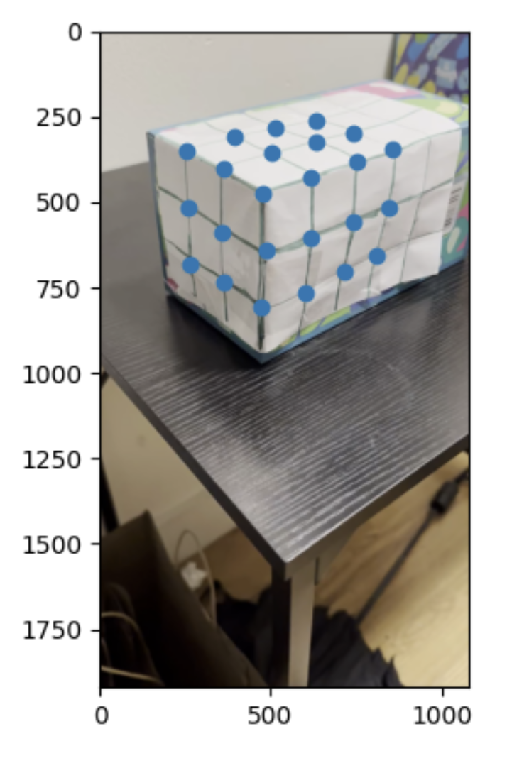
I placed a grid on a rectangular object and manually assigned 3D coordinates to selected points. Adjacent grid points are separated by one unit, and the three visible faces of the object provide variation in x, y, and z. This makes the correspondences useful for estimating a full camera projection matrix rather than a planar-only homography.
Point Tracking
After labeling reference points in the first frame, I tracked them through the video using OpenCV's MedianFlow tracker. Each point is initialized with a small bounding box, then updated frame by frame. Bad tracks and out-of-bounds points are filtered so they do not destabilize the projection estimate.
Projection Matrix Estimation
The camera projection matrix maps a 3D point (X, Y, Z) to a 2D image point (u, v) in homogeneous coordinates:
For each 3D-to-2D correspondence, the homogeneous equation gives two linear constraints on the entries of P. With many tracked points, I solve the resulting least-squares system per frame. This estimates the camera pose and projection jointly enough to place the cube in the image.
Cube Projection and Rendering
I defined the cube by its 3D vertices in the same coordinate system as the calibration grid. For each video frame, those vertices are multiplied by the frame's projection matrix, normalized by homogeneous depth, and connected with line segments using OpenCV drawing operations.
The result is a cube that moves consistently with the object field because both the tracked points and the synthetic cube are expressed in the same world coordinate system.
Additional Implementation Notes
The augmented reality pipeline depends on having enough 3D-to-2D correspondences that are not all coplanar. A planar homography can map one face of the calibration object into the image, but a cube overlay needs a projection that understands depth. By labeling points across the visible 3D structure, the least-squares estimate can recover a projection matrix that maps arbitrary points in the calibration coordinate system to image coordinates.
The projection matrix has eleven effective degrees of freedom because homogeneous scale is arbitrary. Each tracked point supplies two constraints, so using many points gives an overdetermined system. This is important in video because point tracks are noisy: least squares averages over small tracking errors instead of letting any single point dominate the estimate.
Tracking quality is the main source of temporal stability. If a point drifts, the estimated camera matrix can jitter, which makes the rendered cube move unnaturally. Filtering out bad tracks and using a consistent set of reliable points helps the cube remain attached to the physical object. A more advanced version could also smooth the estimated camera pose over time.
Rendering the cube is geometrically simple once calibration is solved. The cube vertices are just 3D points in the calibration coordinate system. Multiplying by the projection matrix gives homogeneous image points; dividing by the third coordinate converts them to pixel coordinates. Drawing line segments between the projected vertices produces the wireframe overlay.
The embedded videos now make the pipeline easier to read as a system: first the original object field, then tracked feature points, then the rendered cube. Seeing those stages together helps diagnose whether errors come from point tracking, projection estimation, or rendering.
Future improvements would use a known marker such as an AprilTag or checkerboard to automate point detection, estimate camera intrinsics separately, and solve for pose with a calibrated PnP method. That would make the overlay more stable and reduce manual setup.
Technical Takeaways and Future Work
The system shows the direct connection between camera calibration and augmented reality. Once a reliable projection matrix is available, rendering synthetic geometry becomes a matter of projecting vertices and drawing edges.
The main limitations are tracker drift and manual point setup. Future improvements would use intrinsic camera calibration, a dedicated fiducial marker, RANSAC for correspondence filtering, and temporal smoothing of the projection matrix.